

Side Load Sensitivity 101
 Load cells come in various shapes and sizes, with different internal mechanisms to measure force. Each design will have inherent side force resistance capabilities that are difficult to quantify with a single, universal specification.
Materials and design features provide load cells with the required robust structure, making them inherently resistant to deformation from off-axis forces. A load cell’s rated capacity often implicitly considers this level of side force resistance, ensuring its reliability in demanding conditions.
Side Force Effect and Load Sensitivity
- Side Force Effect refers to applying a force perpendicular (at 90 degrees) to the intended axial load on a load cell. This misaligned force can occur due to improper load string alignment or imperfections in the testing setup, and understanding this concept can help you identify potential sources of misaligned forces.
- Side Load Sensitivity, a fundamental concept, defines how a load cell’s output is influenced by a side force. In practical terms, it reveals the load cell’s sensitivity to forces applied off its intended axis. A high side load sensitivity can significantly distort the reading, underscoring the practical relevance of this information and the need for a comprehensive understanding of load cell sensitivity.
- Eccentric Load Sensitivity specifies the sensitivity of a load cell to forces applied off-center but still somewhat parallel to its intended axial load.
Understanding these concepts is theoretical knowledge and practical wisdom that can empower you to choose a load cell with the right sensitivity for your application. This knowledge will give you the confidence that you are making an informed decision.
Interface provides detailed information on Side Load Sensitivity percentage and Eccentric Load Sensitivity percentage on the load cell datasheet and online specifications under ACCURACY (Max Error) for these models, making it easier to apply this knowledge and feel confident in your choice.
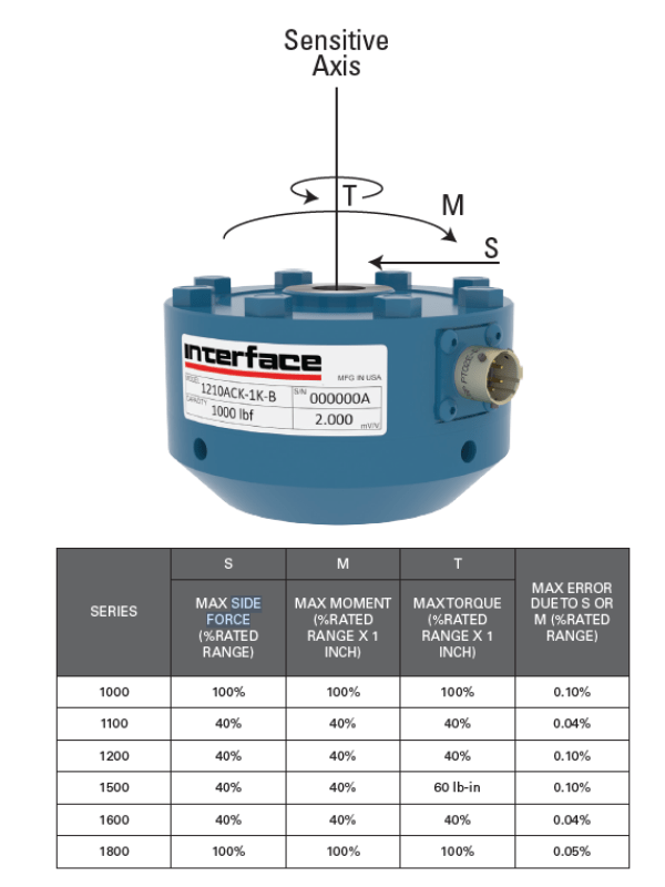 The Interface LowProfile® design provides optimum resistance to extraneous loads, ensuring maximum operation life and minimizing reading errors. The diagram tabulates the maximum allowable extraneous loads that may be applied singularly without electrical or mechanical damage to the cell and the maximum error that can be expected from side forces or bending moments.
Interface offers a large range of load cells that offer side load sensitivity. Here are a few of the most popular models, including those that are eccentric load compensated:
- 1000 Fatigue-Rated Universal LowProfile® Load Cell
- 1000 High Capacity Fatigue-Rated Universal LowProfile® Load Cell
- 1100 Ultra Precision Universal LowProfile® Load Cell
- 1200 Standard Precision Universal LowProfile® Load Cell
- 1208 Flange Standard Precision Universal LowProfile® Load Cell
- 1600 Gold Standard® Calibration Universal LowProfile® Load Cell
- 1800 Platinum Standard® Calibration Universal LowProfile® Load Cell
- 2400 Standard Stainless Steel High Capacity Universal Load Cell
- 3200 Precision Stainless Steel Universal Load Cell
TIP: Use Interface’s Load Cell Selection Guide to review features, capacities, and specifications that fit your testing requirements
Tech Talk: Side Force Effect in Compression Testing
A side force effect in compression testing with load cells refers to a force applied perpendicular to the intended axial compression force. This can happen due to misalignment between the load cell under test and the testing machine’s loading plates.
Alignment is not just a step in testing. It’s an essential factor that can significantly impact the accuracy of your results. Ensure the test load cell undergoing the compression test is precisely centered between the loading plates. A plate (sometimes called platen) is a flat, rigid plate that applies pressure to the test. They apply or receive pressure in various applications. Visual inspection and alignment tools can help you achieve this.
Regular inspection and maintenance of the testing machine are not just routine tasks, it helps to ensure the accuracy of your compression testing. Confirm the loading plates are flat and parallel to each other. Typically, two plates, one fixed and one movable, compress the specimen between them during the test. In compression testing, the plates apply the compressive force to the load cell. Uneven plates can introduce a tilting effect, causing a side force. Regular inspection and maintenance of the testing machine are crucial.
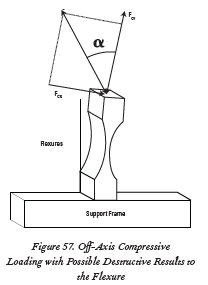 In the compressive testing, the flexure’s reaction, as shown in Figure 57, can be highly destructive, even though the applied force is the same magnitude and is applied along the same line of action as the tensile force because the flexure bends away from the line of action of the applied force.
This tends to increase the side force (FCX) because the flexure bends even more. If the side force exceeds the flexure’s ability to resist the turning motion, the flexure will continue to bend and ultimately fail. Thus, the failure mode in compression is bending collapse, which will occur at a much lower force than can be safely applied in tension.
Several loads can be tolerated simultaneously if the total combined load is not more than 100% of the allowable maximum extraneous load.
Download the Interface Load Cell Field Guide for additional technical examples and resources. Following our 101 Series is a valuable resource.


