Interface Primer Dives Deep into Torque Measurement
 As a follow-up to our recent post, “Torque Measurement Primer Review,” which introduced the foundational concepts of torque measurement, we now examine the intricacies of torque transducers, as outlined in Interface’s free Torque Measurement Primer. This reference will enhance your technical understanding of torque transducers and help you make informed decisions when selecting the right tools for your specific applications.
As a refresher, there are two main types of torque transducers: rotary and reaction. The choice between these two depends on your specific use case. Use Interface’s Torque Transducer Selection Guide to review capacities and dimensions.
- Reaction Torque Transducers measure torque without rotating, making them ideal for static applications.
- Rotary Torque Transducers rotate as part of the system, making them suitable for dynamic applications where the sensor is part of the rotating assembly.
The primer provides an in-depth analysis of the mechanisms and technologies involved in these transducers, including slip rings, rotary transformers, and digital electronics. Each serves distinct functions in different measurement scenarios.
Torque Transducer Mechanical Configurations
Shaft-style transducers can be smooth or keyed for uniform torque introduction. Smooth shafts offer advantages over their keyed counterparts, including more uniform torque introduction into the measuring shaft, ease of assembly and disassembly, and zero backlash.
Flange-style transducers are shorter, with centering pilots commonly used in limited space applications.
TIP! Don’t forget the coupling! The two main categories of coupling are single and double flex, also referred to as half and full couplings. A single-flex coupling has a flex point and allows only angular misalignment. Radial misalignment, perpendicular to the axis of rotation, is not possible. A double flex has two flex points, allowing both angular and radial misalignment.
A coupling designed for smooth shafts will have some clamping method to the shaft. This is commonly accomplished with split collars or shrink-disk-style hubs, which usually include features to aid their removal from the shaft.
Hubs for keyed shafts are more straightforward and cost less than those for smooth shafts, but they can suffer from wear due to backlash, especially in reciprocating applications. To prevent backlash, the hub must be installed on the keyed shaft with an interference fit, usually accomplished by heating the hub before installation or pressing the hub onto the shaft. Use the Torque Coupling Selection Guide.
Torque Transducer Installation Considerations
The installation method significantly impacts your torque transducer’s performance as well. Pay attention to the type of applications you will be testing to determine the installation type you will need:
- Fixed Mounting: This method best suits high RPM applications and requires precise alignment between rotating and stationary parts. It is often used in controlled environments like motor testing.
- Floating Mounting: More forgiving of misalignments, floating mounts reduce the impact of extraneous loads on the sensor, making them ideal for systems with significant radial misalignment or thrust loads.
Rotary torque transducers are either supported on bearings in a housing or bearingless. Bearing-supported designs maintain alignment between the rotating and stationary parts of the sensor and can be easier to mount. Bearingless sensors require the non-rotating part of the sensor to be held in a precisely fixed position relative to the rotating part. Some bearingless sensors are more forgiving of alignment issues than others.
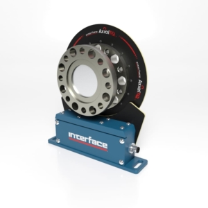
AxialTQ Bearingless Transducer
 Check out the Interface’s AxialTQ to learn about today’s most revolutionary bearingless sensor with no contact between the stator and the rotor. AxialTQ™ torque measurement system redefines the category in function, accuracy, and customizable compatibility. The rotor sensing element and electronics are the heart of the system, and they will be offered at eight torque capacities in five DIN sizes. With the flexible stator and output module mounting capability, the AxialTQ system offers infinite configurations.
AxialTQ Features
- Crash-Proof Design for Maximum Reliability
- Versatile Design for Application Flexibility
- Flexible Configuration
- Simultaneous Analog and Digital Outputs Enables Real-time Control and Data Collection
- Interchangeable Stators and Output Modules to Minimize Parts Inventory
- Wide Range of Standard Components to Match Any Application
AxialTQ Options
- Balanced Rotor to G2.5
- Speed Sensing 60 PPR
- High-Resolution Encoder
- Integrated Couplings
 NEW! AxialTQ In-Line Magnetic Encoder Kit Features and Benefits
- High resolution: <0.125°
- ±1 Increment Repeatability
- Quadrature Differential Signal Output (A, A/, B, B/)
- With Index Signal (I, I/)
- Line Driver (RS422)
Environmental factors such as temperature, moisture, and electrical noise must also be considered when selecting and installing torque transducers. The primer advises on best practices, including using heating blankets or enclosures to protect sensors in extreme temperatures and following grounding and shielding techniques to minimize electrical noise, mainly when using Variable Frequency Drives (VFDs).
Torque measurement can be simple or complex, and choosing the suitable transducer requires a deep understanding of your application’s needs. The Torque Measurement Primer by Interface provides a comprehensive guide to navigate this process and ensure you select the most appropriate tools for your requirements. Save a copy of the reference form, which is available below.
For further assistance or to explore Interface’s torque transducer options, don’t hesitate to consult with their expert Application Engineers or use the Interface Torque Selection Guide online.


