Specifications
Specifications
Dimensions
Dimensions
Connector Pin Diagram
Electrical Connections
Basic Information
- It is recommended that the power supply negative pole be grounded.
- It is possible to supply up to 8 350 ohm load cells, or 16 700 ohm load cells.
- For 4-wire load cells, make a jumper between EX- and REF- and between EX+ and REF+.
- Connect terminal “- SUPPLY” to the RS485 common of the connected instruments in the event that these receive alternating current input or that they have an optically isolated RS485.
- In case of an RS485 network with several devices, it is recommended to activate the 120 ohm termination resistance on the two devices located at the ends of the network.
Wiring Diagram
3 outputs: controlled by setpoint values or by remote device via protocol.
2 inputs (default: input 1= SEMI-AUTOMATIC ZERO; input 2= NET/GROSS): settable to have the following functions: SEMI-AUTOMATIC ZERO, NET/GROSS, PEAK or REMOTE CONTROL.
Terminals Legend
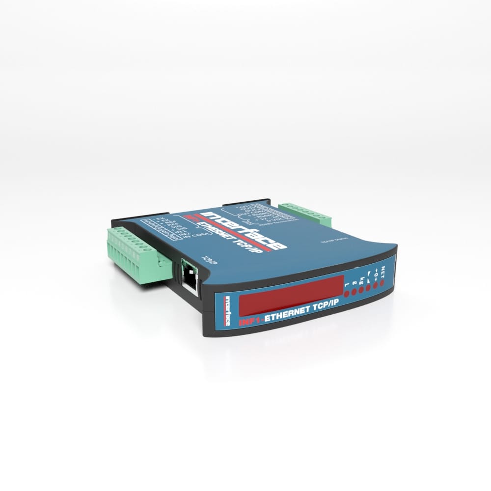
INF1 Legend
| 1 | -LOAD CELL EXCITATION (-EX) |
| 2 | +LOAD CELL EXCITATION (+EX) |
| 3 | +LOAD CELL REF/SENSE |
| 4 | -LOAD CELL REF/SENSE |
| 5 | -LOAD CELL SIGNAL |
| 6 | +LOAD CELL SIGNAL |
| 7 | INPUT No. 1 (+VDC min 5 V max 24 V) |
| 8 | INPUT No. 2 (+VDC min 5 V max 24 V) |
| 9 | INPUT COMMON (-VDC 0 V) |
| 15 | OUTPUT No. 1 |
| 16 | OUTPUT No. 2 |
| 17 | OUTPUT No. 3 |
| 18 | OUTPUT COMMON |
| 19 | RS485: + |
| 20 | RS485: - |
| 21 | +SUPPLY (12/24 VDC) |
| 22 | -SUPPLY (12/24 VDC) RS485: SHIELD,GND |
For more information visit Electrical Wiring Diagrams