Features and Benefits
- LCD display, W x H – 4.6 x 3.4 in (117 x 86 mm)
- Display up to four scale channels per screen with required Legal for Trade information
- 32 scale accumulators
- Millivolt calibration, 5-point linearization and geographical calibration
- NEMA Type 4X/IP66 stainless steel enclosure
- Selectable A/D measurement rate up to 960/second
- 100 setpoints, 30 configurable setpoint types
- 64 K user on-board NV RAM
- Power for 16, 350 ohms load cells per A/D board
- Peak hold
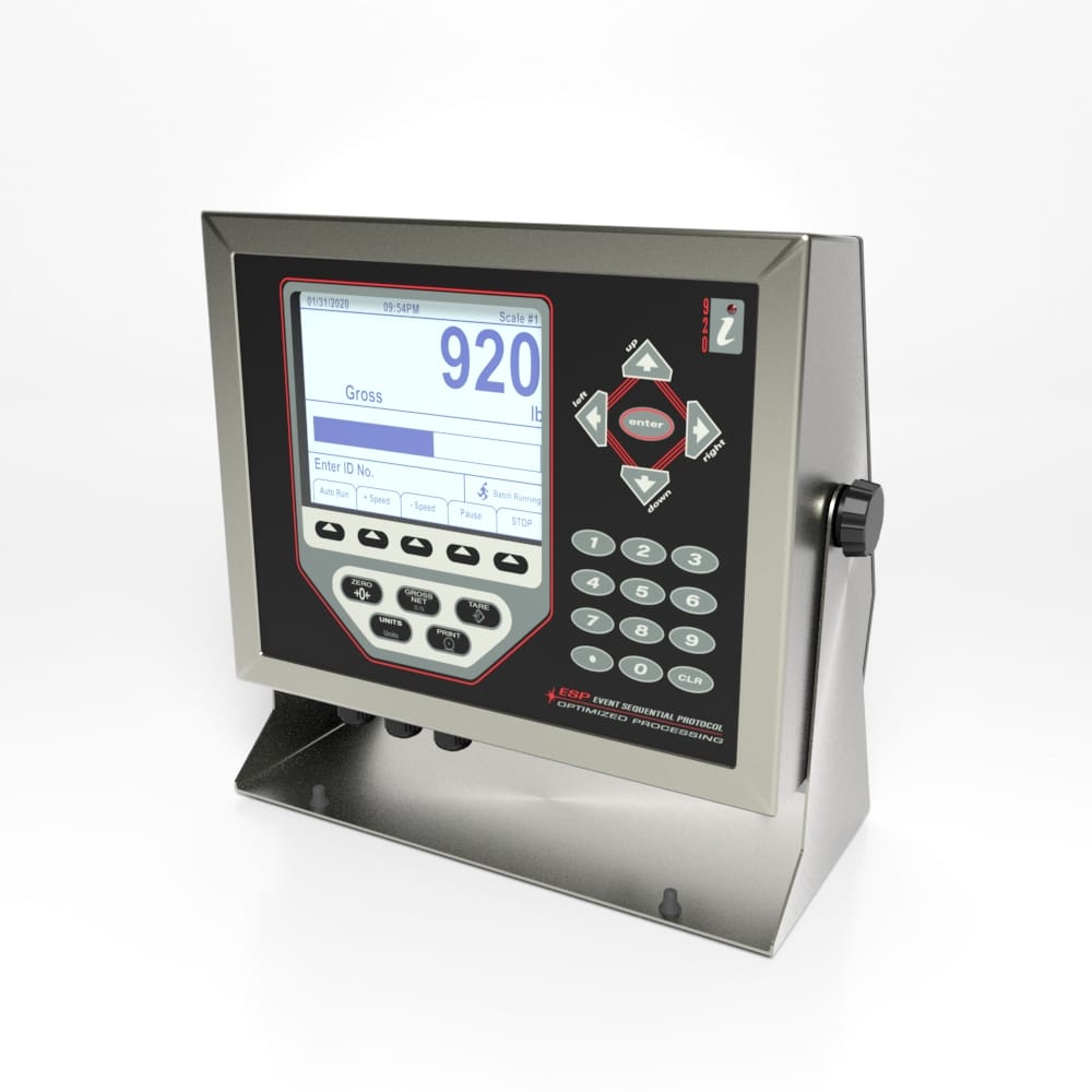
Getting Started –
920i Programmable Weight Indicator Controller
Specifications
Specifications
Connector Pin Diagram
Load Cells
To attach the cable from a load cell or j-box to an installed A/D card, route the cable through the cord grip and ground the shield wire as described in the Interface 920i Technical Manual Section 2.3.2, Page 9.
Remove connector J1 from the A/D card. The connector plugs into a header on the A/D card, see wiring diagram below. Wire the load cell cable from the load cell or j-box to connector J1 as shown in Single-Channel A/D Card Table.
| SINGLE-CHANNEL A/D CARD PINOUT |
| PIN | FUNCTION |
| 1 | + SIGNAL |
| 2 | - SIGNAL |
| 3 | +SENSE |
| 4 | - SENSE |
| 5 | + EXCITATION |
| 6 | - EXCITATION |
- For 6-wire load cell connections to connector J1, remove jumpers JP1 and JP2.
- For 6-wire load cell connections to connector J2 (dual A/D cards), remove jumpers JP3 and JP4.
If using 6-wire load cell cable (with sense wires), remove jumpers JP1 and JP2 before reinstalling connector J1. For 4-wire installation, leave jumpers JP1 and JP2 on. For 6-wire load cell connections on dual-channel A/D cards, remove jumpers JP3 and JP4 for connections to J2.
When connections are complete, reinstall load cell connector on the A/D card and use two cable ties to secure the load cell cable to the inside of the enclosure.
Serial Communications
The four communications ports on the 920i CPU board support full duplex RS-232, 20 mA output, or RS-485 communications at up to 115200 bps.
To attach serial communications cables:
-
- Route the cable through the cord grip.
- Ground the shield wire as described in the refer to the Interface 920i Technical Manual Section 2.3.2, Page 9.
- Remove the serial connector from the CPU board and wire to the connector.
- Once cables are attached, plug the connector into the header on the board.
- Use cable ties to secure serial cables to the inside of the enclosure.
The Serial Port Pinout Table shows the pin assignments for Ports 1, 3, and 4. Port 2 provides DIN-8 and DB-9 connectors for remote keyboard attachment of PS/2-type personal computer keyboards. The DB-9 connector pin assignments for Port 2 are shown in DB-9 Connector Pinout Table below; refer to the Interface 920iTechnical Manual Section 11.3, Page 125 for information about the PS/2 keyboard interface.
| SERIAL PORT PINOUT |
| CONNECTOR | PIN | SIGNAL | PORT |
| J11 | 1 | GND | 1 |
| 2 | RS-232 RxD |
| 3 | RS-232 TxD |
| J9 | 1 | GND / -20mA OUT | 3 |
| 2 | RS-232 RxD |
| 3 | RS-232 TxD |
| 4 | +20mA OUT |
| J10 | 1 | GND / -20mA OUT | 4 |
| 2 | RS-232 RxD |
| 3 | RS-232 TxD |
| 4 | +20mA OUT |
| 5 | RS-485 A |
| 6 | RS-485 B |
Serial ports are configured using the SERIAL menu. refer to the Interface 920i Technical Manual Section 3.2.2, Page 38 for configuration information. An optional dual-channel serial communications expansion card, PN 67604, is available. Each serial expansion card provides two additional serial ports, including one port that supports RS-485 communications. Both ports on the expansion card can support RS-232 or 20mA connections.
| DB-9 CONNECTOR PINOUT |
| PIN | SIGNAL |
| 2 | TxD |
| 3 | RxD |
| 5 | GND |
| 7 | CTS |
| 8 | RTS |
| J4 (OPTIONAL KEYBOARD CONNECTOR) PINOUT |
| PIN | COLOR | SIGNAL |
| 1 | BROWN | CLOACK |
| 2 | CLEAR | +5v |
| 3 | YELLOW | GND |
| 4 | RED | DATA |
USB Communications (Port 2)
The USB interface provides type-A and type-B connectors. Compatible devices using a type-A connector include a flash drive, keyboard, USB hub, and label and ticket printers. The host PC uses a type-B connector.
Digital I/O
Digital inputs can be set to provide many indicator functions, including all keypad functions. Digital inputs are active low (0 VDC), inactive high (5 VDC).
Digital outputs are typically used to control relays that drive other equipment. Outputs are designed to sink, rather than source, switching current. Each output is a normally open collector circuit, capable of sinking 24 mA when active. Digital outputs are wired to switch relays when the digital output is active (low, 0 VDC) with reference to a 5 VDC supply.
| J2 PINOUT |
| PIN | SIGNAL |
| 1 | GND |
| 2 | DIO 1 |
| 3 | DIO 2 |
| 4 | DIO 3 |
| 5 | DIO 4 |
| 6 | DIO 5 |
| 7 | DIO 5 |
| 8 | DIO 6 |
Digital inputs and outputs are configured using the DIG I/O menu. See Section 3.2.6 on page 53 for configuration information.
An optional 24-channel digital I/O expansion card, PN 67601, is available for applications requiring more digital I/O channels.
Note: Digital I/O points can be configured to count active pulse inputs by setting them to PROGIN (DIGIN menu) and using the iRite DigInSsBbActivate handler. However, the fastest pulse rate that can be counted using a digital input is 10Hz (10 pulses per second). More demanding applications can use the pulse input option card (PN 67603) to count pulses in the 4–4000Hz range.
For more information visit Electrical Wiring Diagrams 


 Aerial Lift Overload Control
  Chemical Reaction-Mixing
  Road Bridge Lift Monitoring
  Chocolate Melanger Torque
  Proppant Silo System


