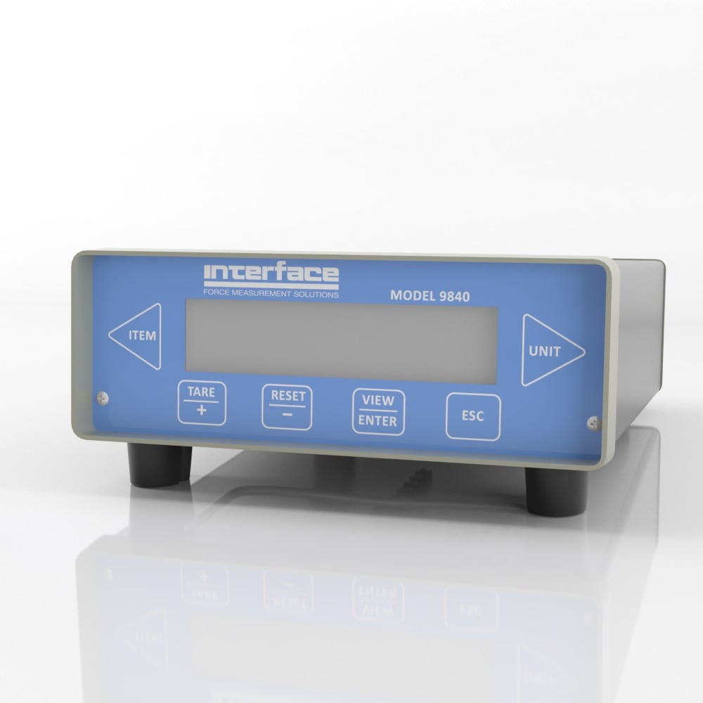
Specifications
Specifications
International System of Units (SI) dimensions and capacities are provided for conversion only. Standard products have U.S. capacities and dimensions. SI capacities available upon special request and at an additional cost.
Connector Pin Diagram
Load Cell Connectors
|
DB9 FEMALE CONNECTOR PINOUT |
|
PIN |
FUNCTION |
|
1 |
EXCITATION - HIGH |
|
2 |
SENSE - HIGH¹ |
|
3 |
CELL OUTPUT - HIGH |
|
4 |
CELL OUTPUT - LOW |
|
5 |
SENSE - LOW¹ |
|
6 |
EXCITATION - LOW |
|
7 |
AUTO ID/TEDS OPTION - A |
|
8 |
AUTO ID/TEDS OPTION - B |
|
9 |
CHASSIS GND |
Notes:
- If the sense lines are not used, SENSE – HIGH must be tied to EXCITATION – HIGH and SENSE – LOW must be tied to EXCITATION – LOW.
- Incorrect wiring of these ports can cause damage to the internal circuitry of the unit. Please contact Interface if you have questions or need assistance with these configurations.
Serial Port Connector
|
DB 15 FEMALE CONNECTOR PINOUT |
|
PIN |
FUNCTION |
|
1 |
TXD |
|
2 |
RXD |
|
3 |
NO CONNECT |
|
4 |
SERIAL GND |
|
5 |
TXD+ (PRINTER) |
|
6 |
TXD- (PRINTER) |
|
7 |
RXD- (RS485) |
|
8 |
RXD+ (RS485) |
|
9 |
NO CONNECT |
|
10 |
SERIAL GND |
|
11-13 |
NO CONNECT |
|
14 |
TXD+ (RS485) |
|
15 |
TXD- (RS485) |
Notes:
- Pins 1 through 4 are used for RS232 ASCII command set communications. Use 8 data bits, no parity, 1 stop, and set the baud rate using the Com baud rate entry on the System Options menu.
- The printer uses RS422 differential signaling on pins 5, 6 and 10. Baud rate for the printer is selectable using the Printer Baud entry on the System Options menu.
- Pins 7, 8, 14 and 15 are used for RS485 ASCII command set communications. Use 8 data bits, no parity, 1 stop, and set the baud rate using the Com baud rate entry on the System Options menu.
Digital I/O Connector
|
HIGH DENSITY 26 FEMALE CONNECTOR PINOUT |
|
PIN |
FUNCTION |
|
1 |
LIM 1 A¹ |
|
2 |
LIM 1 B¹ |
|
3 |
LIM 2 A |
|
4 |
LIM 2 B |
|
5 |
LIM 3 A |
|
6 |
LIM 3 B |
|
7 |
LIM 4 A |
|
8 |
LIM 4 B |
|
9 |
ISO IN 1 - HIGH² |
|
10 |
ISO IN 1 - LOW² |
|
11 |
ISO IN 2 - HIGH |
|
12 |
ISO IN 2 - LOW |
|
13 |
ISO IN 3 - HIGH |
|
14 |
ISO IN 3 - LOW |
|
15 |
ISO IN 4 - HIGH |
|
16 |
ISO IN 4 - LOW |
|
17 |
KEYLOCK³ |
|
18 |
GND |
|
19 |
ENCODER CHA-L⁴ |
|
20 |
ENCODER CHA |
|
21 |
GND |
|
22 |
ENCODER CHB-L |
|
23 |
ENCODER CHB |
|
24 |
GND |
|
25 |
GND |
|
26 |
+12 VDC (+5 VDC OPTIONAL⁴) |
Notes:
- Limits are optically isolated solid state switches that can control AC or DC voltage. Peak blocking voltage is 350V, maximum continuous current is 120 mA.
- Digital inputs are opto-isolated with internal current limiting resistors. Voltage range is +4 to +22 VDC on the “HI” input with respect to the “LO” input. Other voltage ranges are possible with added external resistors, contact Interface for details. If isolation is not required these inputs may be operated using the +12 VDC supplied on pin 26 and the GND on pin 24.
- The keylock input will be in the “unlocked” state if left unconnected. Tie this pin to GND to “lock” it. When locked the setup of the Model 9840 cannot be changed (you cannot enter Setup mode).
- The encoder inputs are intended for use with a +12 VDC quadrature encoder. For single ended signaling use the CHA and CHB pins, the CHA-L and CHB-L pins are provided for differential signals. The encoder can be supplied with the +12 VDC and GND available on pins 26 and 24. The Model 9840 will also accept +5 VDC encoder inputs but these MUST be differential. Single ended +5 VDC inputs are not supported on the standard unit. Options for +5 VDC encoders are available. Pin 26 will supply +5 VDC for this option and must be ordered accordingly.
OPTION ~ Remote Freeze Cable
P/N CABLE 988278-010 Remote Actuation Push-Button Display Hold/Freeze Cable (Cable shown is approximately 10 feet)
The cable to support the digital input for display HOLD/FREEZE actuation must connect to the 26 pin DIGITAL I/O connector located on the rear panel of the Model 9840.
The connection is to actuate digital input #4, signals ISO IN 4 – HI (pin 15) and ISO IN 4 – LO (pin16).
To accomplish this, signal ISO IN 4 – LO (pin16) is tied to GND, (pin 25).
A pushbutton switch is then installed across the signal ISO IN 4 – HI (pin 15) and the +12VDC (pin 26). In parallel with the pushbutton switch, a .01uf ceramic capacitor is installed for debouncing.
Digital I/O Connector
- The source and scaling of ANALOG – OUT is selected through the menus.
- The HIGH BANDWIDTH – OUT is a buffered analog output permanently connected to the load cell channel.
- If the 4-20 mA Option is purchased.
|
DB9 MALE CONNECTOR PINOUT |
|
PIN |
FUNCTION |
|
2 |
ANALOG - OUT¹ |
|
3 |
ANALOG - GND |
|
4 |
HIGHBANDWIDTH - OUT² CHANNEL A |
|
5 |
4-20 mA - OUT³ CHANNEL A |
|
6 |
2ND ANALOG - OUT¹ (OPTIONAL) |
|
7 |
4-20 mA - OUT³ CHANNEL B |
|
8 |
HIGHBANDWIDTH - OUT² CHANNEL B |
|
9 |
NO CONNECT |
USB Connector
|
USB CONNECTOR PINOUT |
|
PIN |
FUNCTION |
DESCRIPTION |
|
1 |
VCC |
+5 VDC |
|
2 |
D - |
DATA - |
|
3 |
D + |
DATA + |
|
4 |
GND |
GROUND |
For more information visit Electrical Wiring Diagrams


 Pneumatic Actuator Seal Pressure