Features and Benefits
- ±10V and 4-20mA
- 4 independent channels
- For use with model 3AXX series 3-axis load cells
- Can be used with up to any 4 standard load cells (with mV/V output)
Amplifier channels have fixed gain settings and are not adjustable for specific load cell output signals. Because of this, the amplifier output will typically be less than the nominal 10V or 20mA at load cell full scale.
Specifications
Specifications
Dimensions
Dimensions
Connector Pin Diagram
View of Socket Side
| WIRING DIAGRAM FOR 5-PIN SOCKET M12X1, TYPE 763 |
| PIN | DESCRIPTION | COLOR |
| 2 | -Us Negative Bridge Power Supply | WHITE | WHITE |
| 1 | +Us Positive Bridge Power Supply | BROWN | BROWN |
| 3 | +Ud Positive Defferential Inpout | GREEN | BLUE |
| 4 | -UD Negative Defferential Inpout | YELLOW | BLACK |
| 5 | AUX Connected to Quarter Bridge 350 Ohm (QB) | GRAY | GRAY |
Six-wire technology is not possible for M12 socket variant.
In quarter bridge and half bridge mode, the internal half bridge completion must be activated via the solder bridge on the circuit board (also possible in the factory as a free order option).
Socket Spring Contacts
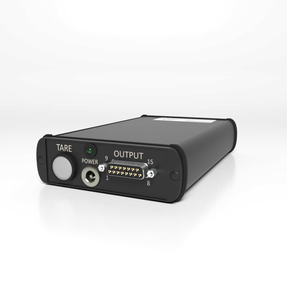
| WIRING DIAGRAM FOR OUTPUT SOCKET 15-PIN SUB-D SOCKET |
| BSC4A ASSIGNMENT | 15-PIN SUB-D (PIN NO./COLOR) |
| GNDio | 1 / Black |
| Zero-Point Adjustment (Joint) | 8 / Purple |
| Supply Voltage | 9 / Gray |
| Channel | 1 | 2 | 3 | 4 |
| Output Voltage | 2 / Brown | 5 / Yellow | 15 / Red-White | 12 / Light Green |
| Output Current | 3 / Red | 6 / Green | 14 / Brown-White | 11 / Pink |
| Ground | 4 / Orange | 7 / Blue | 13 / Black-White | 10 / White |
The colors correspond to the core colors of the supplied 3-meter cable with 15-pin connector SubD15.
Automatic Zero Adjustment
Automatic Zero-adjustment is operated via push button or via digital input. Advice: the GNDio PIN 1 for digital input with PIN 8 is isolated from analog Ground PIN4. Analog grounds PIN4, PIN7, PIN13, PIN10 are connected.
Connect GNDio (PIN1) permanently with Ground (PIN4) and connect Supply Voltage (PIN9) via Relays or button with PIN8 for remote-controlled zero adjustment.
| DESCRIPTION | COLOR | PIN |
| GNDio for Digital Input | BLACK | 1 |
| Zero-Adjustment Input | PURPLE | 8 |
| Supply Voltage Output | GRAY | 9 |
The colors correspond to the core colors of the supplied 3-meter cable with 15-pin connector Sub-D15.
Wiring Diagram for 37-Pin Sub-D Socketa
37-Pin Sub-D, Female
wpDataTable with provided ID not found!
- Half bridge completion must be activated at the same time.
- The negative differential input (25, 7,16, 34) must be connected to the corresponding half bridge completion (24, 6,15, 33).
The automatic zero-point setting is done via push buttons or via the digital input. PIN 28 or 10 or 19 or 37.
Note: The GNDio PINs for the automatic zero adjustment are separated from the analog ground. Permanently connect GNDio (PIN1) to the ground of the supply voltage and connect the supply voltage, but at least 3.5V with PIN 28 or 10 or 19 or 37 for remote zero setting.
Wiring Diagram of a Full Bridge to Sub-D37, Channel 1-4
Wiring Diagram of a Half Bridge to Sub-D37, Channel 1-4 Wiring Diagram of a Quarter Bridge to Sub-D37, Channel 1-4 Wiring Diagram for a Full Bridge M12 Variant Wiring Diagram for Quarter Bridges and Half Bridges M12 Variant Please note: For quarter and half-bridge operation, the internal half-bridge supplement must be activated by solder bridges on the printed circuit board (also possible at the factory). Adjusting the Sensitivity
The sensitivity of channels 1 to 4 can be adjusted. On the circuit board of the BSC4A, each channel has a jumper post field with 4 plug options in total.
For more information visit Electrical Wiring Diagrams 


 Prosthetic Foot Performance
  Sanding Machine Force Monitoring


