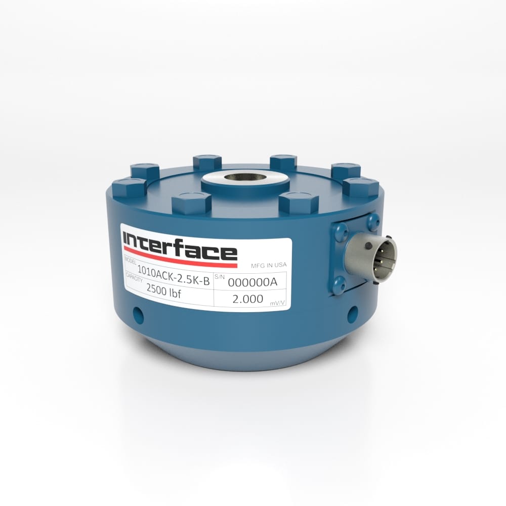
1000 Fatigue-Rated Universal LowProfile® Load Cell
Eccentric Load Compensated High Safe Overload
250 lbf to 50K lbf
1.25 kN to 225 kN
Model 1000 series is a fatigue-rated low profile load cell with 300% safe overload, extremely low moment sensitivity of 0.1%/in and a higher fatigue life. If you need to measure 1 pound (4.45N) or 1 million pounds (4500kN) of force, Interface load cells can do it. With many variants and configurations our fatigue-rated load cells provide up to 100 million fully rendered cycles. The gaged sensors in every load cell are individually inspected and tested, and certified to meet our rigid standards.
Options Available for 2nd, 3rd Bridge and Overload Protection.
Models 1010, 1020, and 1032 are available.
Model 1000 series is a fatigue-rated low profile load cell with 300% safe overload, extremely low moment sensitivity of 0.1%/in and a higher fatigue life. If you need to measure 1 pound (4.45N) or 1 million pounds (4500kN) of force, Interface load cells can do it. With many variants and configurations our fatigue-rated load cells provide up to 100 million fully rendered cycles. The gaged sensors in every load cell are individually inspected and tested, and certified to meet our rigid standards.
Please Login to view pricing and product downloads
Need a quote or looking to purchase this item?
Login, scroll to see your model descriptions and SKU part number, then use the Request for Quote button to submit your request.
Features and Benefits
- Capacities from 250 lbf to 50K lbf (1.11 kN to 222 kN)
- Proprietary Interface temperature compensated strain gages
- Performance to 0.03%
- Eccentric load compensated
- Low deflection
- 0.0008%/°F (.0015%/°C) temp. effect on output
- Barometric compensation
- Shunt calibration
- E74 NIST Traceable Tension and Compression Calibration (Optional)
Specifications
Specifications
|
PARAMETERS |
MODEL |
|
1010 |
1010 |
1020 |
1032 |
|
CAPACITY |
|
Measuring Range |
U.S. (lbf) |
250, 500, 1K |
2.5K, 5K |
7.5K, 10K, 12.5K, 25K |
50K |
|
Metric (kN) |
1.25, 2.5, 5 |
12.5, 25 |
33.4, 44.5, 50, 125 |
225 |
|
Accuracy - (Max Error) |
|
Static Error Band – %FS |
±0.03 |
±0.03 |
±0.03 |
±0.03 |
|
Nonlinearity – %FS |
±0.04 |
±0.04 |
±0.04 |
±0.04 |
|
Hysteresis – %FS |
±0.03 |
±0.03 |
±0.03 |
±0.03 |
|
Nonrepeatability – %RO |
±0.02 |
±0.02 |
±0.02 |
±0.02 |
|
Creep, in 20 min – % |
±0.025 |
±0.025 |
±0.025 |
±0.025 |
|
Side Load Sensitivity – % |
±0.1 |
±0.1 |
±0.1 |
±0.1 |
|
Eccentric Load Sensitivity – % / in |
±0.1 |
±0.1 |
±0.1 |
±0.1 |
|
Temperature |
|
Compensated Range |
°F |
+15 to +115 |
+15 to +115 |
+15 to +115 |
+15 to +115 |
|
°C |
-10 to +45 |
-10 to +45 |
-10 to +45 |
-10 to +45 |
|
Operating Range |
°F |
-65 to +200 |
-65 to +200 |
-65 to +200 |
-65 to +200 |
|
°C |
-55 to +90 |
-55 to +90 |
-55 to +90 |
-55 to +90 |
|
Effect on Zero – %RO / deg |
°F |
±0.0008 |
±0.0008 |
±0.0008 |
±0.0008 |
|
°C |
±0.0015 |
±0.0015 |
±0.0015 |
±0.0015 |
|
Effect on Output – % / deg |
°F |
±0.0008 |
±0.0008 |
±0.0008 |
±0.0008 |
|
°C |
±0.0015 |
±0.0015 |
±0.0015 |
±0.0015 |
|
Electrical |
|
Rated Output – mV/V (Nominal) |
1.0 |
2.0 |
2.0 |
2.0 |
|
Excitation Voltage – VDC MAX |
20 |
20 |
20 |
20 |
|
Bridge Resistance – Ohm (Nominal) |
350 |
350 |
350 |
350 |
|
Zero Balance – %RO |
±1.0 |
±1.0 |
±1.0 |
±1.0 |
|
Insulation Resistance – Megohm |
5000 |
5000 |
5000 |
5000 |
|
Mechanical |
|
Safe Overload – %CAP |
±300 |
±300 |
±300 |
±300 |
|
Deflection @ RO |
in |
0.0005 |
0.001 |
0.001 |
0.002 |
|
mm |
0.013 |
0.025 |
0.025 |
0.050 |
|
Optional Base – P/N (Metric) |
B101 (M) |
B102 (M) |
B103 (M) |
B112 (M) |
|
Natural Frequency – kHz |
5.0, 6.9, 9.8 |
6.6, 9.4 |
6.5, 7.0 |
5.8 |
|
Weight |
lbs |
1.5 |
3.3 |
9.5 |
26 |
|
kg |
0.7 |
1.5 |
4.3 |
12 |
|
Calibration |
Tension & Compression |
|
Material |
Aluminum |
Alloy Steel |
International System of Units (SI) dimensions and capacities are provided for conversion only. Standard products have U.S. capacities and dimensions. SI capacities available upon special request and at an additional cost.
Dimensions
Dimensions
1000 FATIGUE-RATED LOWPROFILE® LOAD CELL Dimensions
|
See Drawing |
Model |
|
1010 |
1020 |
1032 |
|
Capacity |
|
U.S. (lbf) |
Metric (kN) |
U.S. (lbf) |
Metric (kN) |
U.S. (lbf) |
Metric (kN) |
|
250, 500, 1K, 2.5K, 5K |
1.25, 2.5, 5, 12.5, 25 |
7.5K, 10K, 12.5K, 25K |
33.4, 44.5, 50, 125 |
50K |
225 |
|
in |
mm |
in |
mm |
in |
mm |
|
(1) |
Ø4.13 |
Ø104.8 |
Ø6.06 |
Ø153.9 |
Ø8.00 |
Ø203.2 |
|
(2) |
1.38 |
34.9 |
1.75 |
44.5 |
2.50 |
63.5 |
|
(3) |
1.25 |
31.7 |
1.63 |
41.4 |
2.25 |
57.2 |
|
(4) |
Ø1.34 |
Ø34.0 |
Ø2.65 |
Ø67.3 |
Ø3.76 |
Ø95.2 |
|
(5) |
Ø3.50 |
Ø88.9 |
Ø5.13 |
Ø130.3 |
Ø6.50 |
Ø165.1 |
|
(6) |
22.5° |
22.5° |
15.0° |
15.0° |
11.25° |
11.25° |
|
(7) |
Ø0.28 |
Ø7.1 |
Ø0.41 |
Ø10.4 |
Ø0.53 |
Ø13.5 |
|
8 Places |
12 Places |
16 Places |
|
(8) |
5/8-18 UNF-3B ↧ 1.12 |
M16x2-4H ↧ 28.4 |
1 1/4-12 UNF-3B ↧ 1.40 |
M33x2-4H ↧ 35.6 |
1 3/4-12 UNF-3B ↧ 2.15 |
M42x2-4H ↧ 54.6 |
|
(9) |
0.20 |
5.1 |
0.30 |
7.6 |
0.40 |
10.2 |
|
(10) |
1.13 |
28.6 |
1.75 |
44.5 |
2.00 |
50.8 |
|
(11) |
0.03 |
0.8 |
0.03 |
0.8 |
0.03 |
0.8 |
|
(12) |
Ø1.25 |
Ø31.8 |
Ø2.25 |
Ø57.2 |
Ø3.00 |
Ø76.2 |
|
(13) |
5/8-18 UNF-3B ↧ 0.87 |
M16x2-4H ↧ 22.1 |
1 1/4-12 UNF-3B ↧ 1.40 |
M33x2-4H ↧ 35.6 |
1 3/4-12 UNF-3B ↧ 1.75 |
M42x2-4H ↧ 44.5 |
International System of Units (SI) dimensions and capacities are provided for conversion only. Standard products have U.S. capacities and dimensions. SI capacities available upon special request and at an additional cost.
Connector Pin Diagram
|
CONNECTOR PINOUT |
INTEGRAL CABLE MODELS |
|
PIN |
4 WIRE (C1) |
4 WIRE (C1 WITH TEDS OPTION) |
COLOR |
FUNCTION |
|
A |
+ EXCITATION |
+ EXCITATION |
RED |
+ EXCITATION |
|
B |
+ SIGNAL |
+ SIGNAL |
GREEN |
+ SIGNAL |
|
C |
- SIGNAL |
- SIGNAL |
WHITE |
- SIGNAL |
|
D |
- EXCITATION |
- EXCITATION |
BLACK |
- EXCITATION |
|
E |
N/C |
TEDS DATA |
WHITE/RED |
+ SENSE |
|
F |
N/C |
TEDS GROUND |
WHITE/BLACK |
- SENSE |
|
|
WHITE/YELLOW |
SHUNT CAL |
|
SHIELD |
N/C |
|
ALL READ UPSCALE IN TENSION |
|
LOAD CELL INTERGRAL CABLES |
|
CABLE TYPE |
WIRE SIZE |
NUMBER OF WIRES |
SHEILD |
CABLE LENGTH |
DESCRIPTION |
|
A |
22 AWG |
7 |
BRAID |
10 FT (3 M) |
HEAVY-DUTY, PVC JACKET |
For more information visit Electrical Wiring Diagrams


 Automotive Head Rest Testing
  Press Load Monitoring